CMP Slurry Filtration
Particle Control, Yield Protection, and Process Stability in Semiconductor CMP
1. Introduction
CMP slurry filtration is one of the most underestimated yet yield-critical elements in semiconductor manufacturing. While slurry formulations receive extensive attention, filtration systems ultimately determine whether abrasive particles remain controlled or become defect generators.
At advanced technology nodes, even sub-100 nm particle excursions can result in fatal defects, including metal scratches, dielectric gouging, and line bridging. As such, filtration is not merely a maintenance component, but a process control variable.
This white paper provides a systematic engineering framework for CMP slurry filtration, linking particle physics, chemistry stability, defect mechanisms, and high-volume manufacturing (HVM) requirements.
For CMP slurry fundamentals, refer to:
CMP Slurry – Semiconductor Polishing Materials
2. Why Filtration Is Critical in CMP
CMP slurry filtration performs three essential functions:
- Removal of oversized abrasive agglomerates
- Capture of foreign particles generated in the slurry loop
- Stabilization of particle size distribution (PSD)
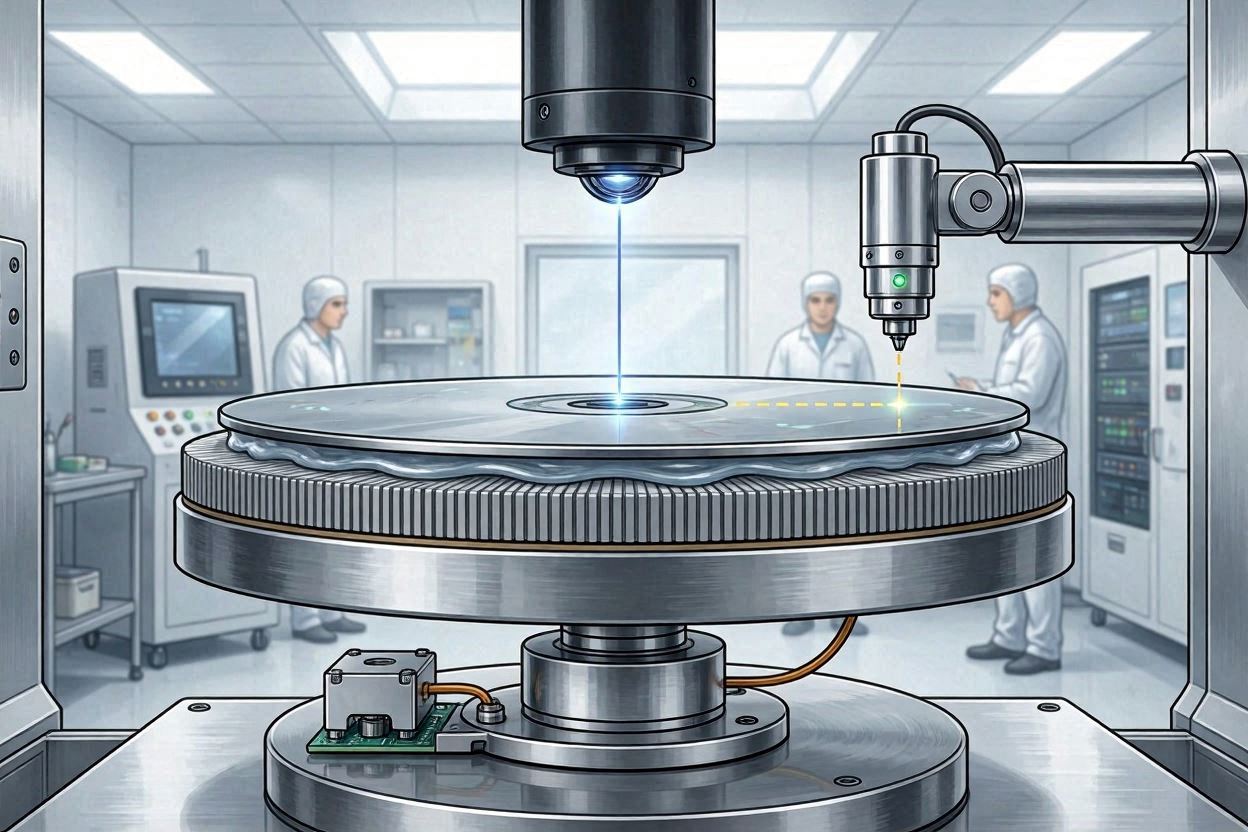
Unlike other wet processes, CMP operates under direct mechanical contact between wafer, pad, and slurry. Any particle exceeding the designed abrasive size can transition from a polishing agent to a scratching tool.
3. Particle Sources in CMP Slurry Systems
3.1 Native Abrasive Agglomeration
Colloidal abrasives are thermodynamically metastable. Changes in pH, ionic strength, or shear conditions can induce agglomeration.
3.2 Chemical Precipitation
Metal ions dissolved during CMP may re-precipitate as metal hydroxides or oxides when local chemistry shifts occur.
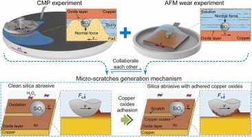
3.3 Mechanical Generation
- Pad debris
- Tool wear particles
- Pump-induced shear fragments
3.4 External Contamination
Improper handling, container shedding, and filter housing degradation contribute to particle ingress.
4. Particle Size vs Defect Mechanisms
| Particle Size | Primary Defect Mode | Yield Impact |
|---|---|---|
| < 50 nm | Minor surface roughness | Low |
| 50–150 nm | Micro-scratches | Moderate |
| 150–300 nm | Visible scratches | High |
| > 300 nm | Gouging, line damage | Critical |
This relationship underpins the rationale for sub-micron filtration in advanced CMP processes.
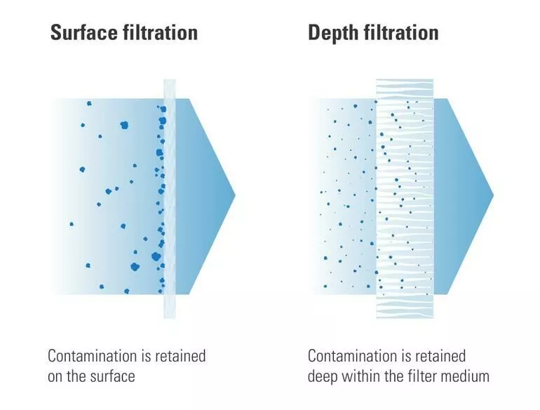
5. CMP Slurry Filter Technologies
5.1 Depth Filters
Depth filters capture particles throughout the filter matrix and provide high dirt-holding capacity.
5.2 Membrane Filters
Membrane filters offer sharp cut-off characteristics and are preferred for final point-of-use (POU) filtration.
5.3 Pleated Filters
Pleated designs increase surface area, reducing pressure drop and extending lifetime.
6. Filter Pore Size Selection Strategy
| Process Node | Abrasive Size | Recommended Pore Size |
|---|---|---|
| > 90 nm | 100–200 nm | 1.0 µm |
| 45–28 nm | 50–100 nm | 0.5 µm |
| < 14 nm | 30–70 nm | 0.2 µm |
Over-filtration risks abrasive depletion, while under-filtration increases defectivity.
7. Chemical Compatibility & Slurry Stability
Filter materials must remain chemically inert under slurry conditions:
- Oxidizers (H2O2, persulfates)
- Low pH (metal CMP)
- Chelating agents
| Filter Material | Chemical Compatibility | Typical Use |
|---|---|---|
| PTFE | Excellent | Metal CMP |
| PVDF | Good | Cu / W CMP |
| Nylon | Moderate | Oxide CMP |
8. Experimental Data & Filtration Performance
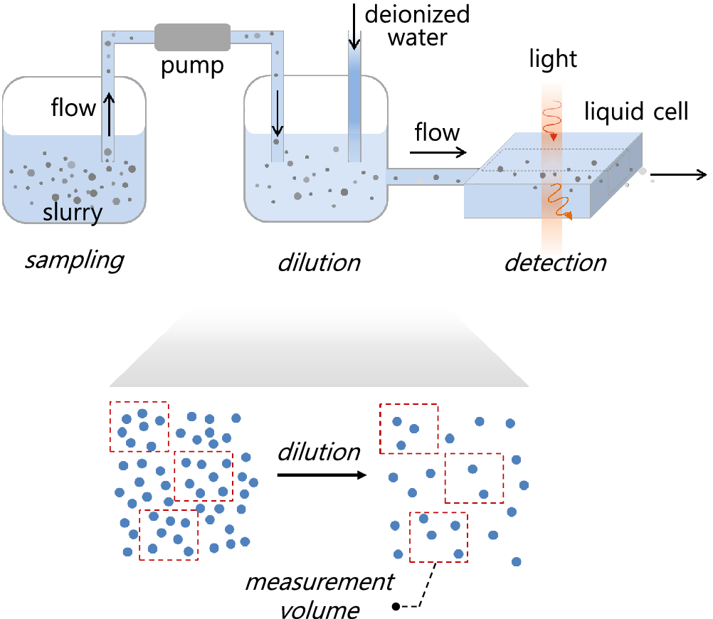
Experimental data consistently show that sub-0.5 µm filtration reduces scratch density by over 70% in metal CMP processes.
9. Filtration Process Window
CMP slurry filtration must operate within a narrow process window balancing:
- Particle removal efficiency
- Pressure drop stability
- Slurry lifetime
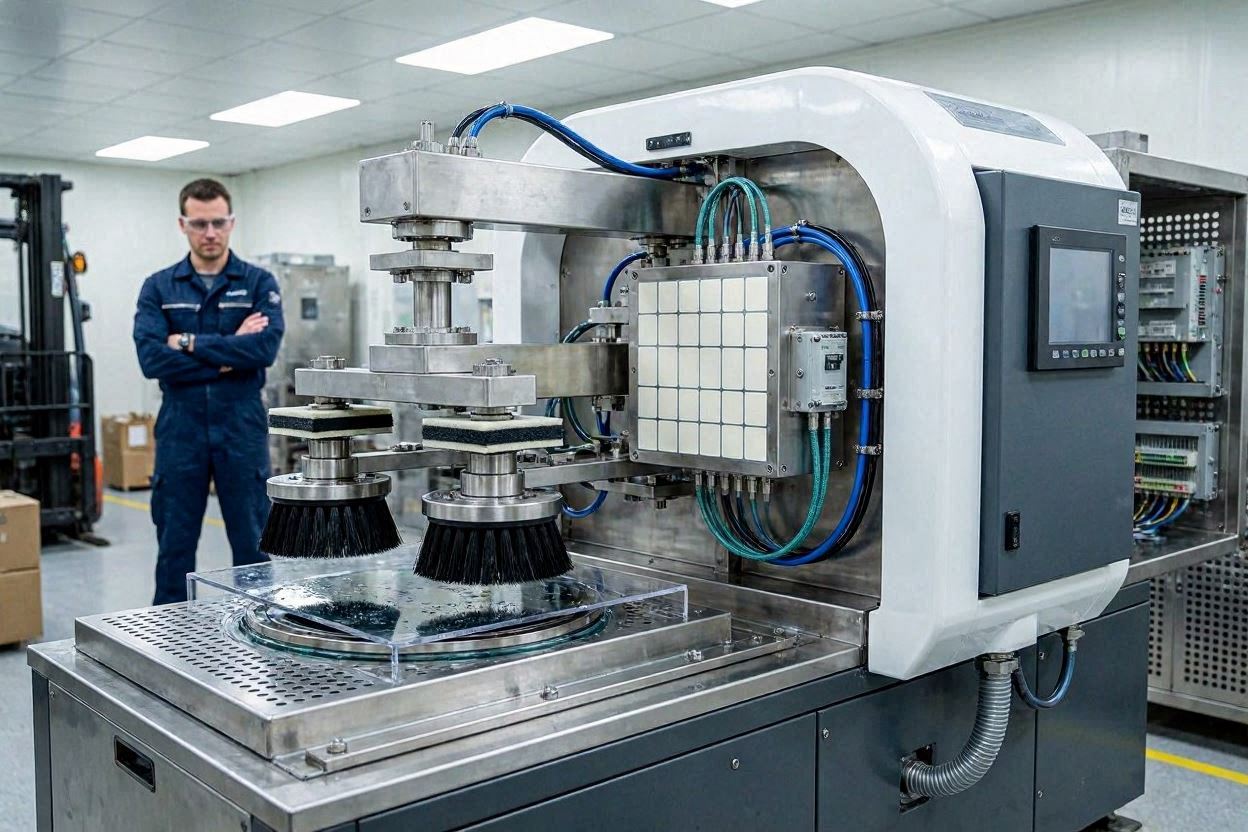
10. Integration with CMP Tools
Filtration systems are typically integrated at:
- Bulk slurry supply
- Recirculation loops
- Point-of-use (POU)
POU filtration provides the most direct defect control but requires frequent monitoring.
11. Filtration Failure Modes & Root Cause Analysis
11.1 Rapid Pressure Drop Increase
Indicates excessive particle loading or slurry instability.
11.2 Sudden Scratch Excursion
Often caused by filter rupture or bypass leakage.
11.3 MRR Drift
May indicate over-filtration and abrasive depletion.
12. HVM Filtration Strategy
- Multi-stage filtration architecture
- Real-time pressure monitoring
- Scheduled filter replacement
HVM success depends on treating filtration as a process variable rather than a consumable.
13. Future Trends
Future CMP slurry filtration developments include:
- Smart filters with particle sensing
- Lower extractables materials
- Node-specific filtration standards