CMP Slurry Filters
Filter Media, Housing Design, and Point-of-Use Control in Semiconductor CMP
1. Overview of CMP Slurry Filters
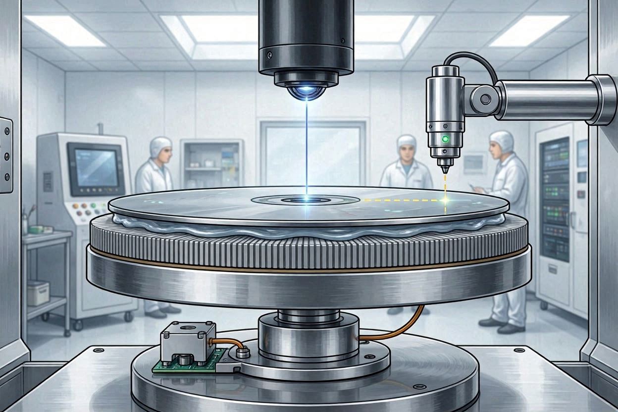
CMP slurry filters are precision components designed to remove oversized particles, agglomerates, and foreign contaminants from slurry delivery systems. Unlike generic liquid filtration, CMP filters must operate under chemically aggressive environments while maintaining ultra-low defectivity.
In advanced semiconductor nodes, filters are no longer passive consumables but active yield enablers.
For slurry fundamentals, refer to:
CMP Slurry Knowledge Hub
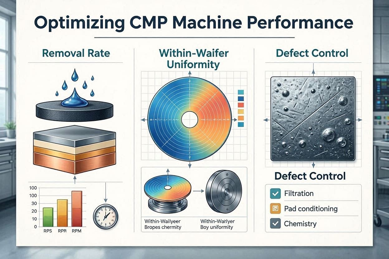
2. Role of Filters in CMP Yield Control
Filters influence CMP performance through three mechanisms:
- Particle size distribution stabilization
- Suppression of scratch-inducing particles
- Protection against system-generated contamination
3. Filter Media Materials
3.1 PTFE (Polytetrafluoroethylene)
PTFE filters offer excellent chemical resistance and minimal extractables, making them ideal for metal CMP processes.
3.2 PVDF (Polyvinylidene Fluoride)
PVDF provides a balance between chemical compatibility and mechanical strength.
3.3 Nylon
Nylon filters are commonly used in oxide CMP but are limited in low-pH metal applications.
| Material | Chemical Resistance | Extractables | Typical Application |
|---|---|---|---|
| PTFE | Excellent | Ultra-low | Cu / W CMP |
| PVDF | Very Good | Low | Metal CMP |
| Nylon | Moderate | Moderate | Oxide CMP |
4. Absolute vs Nominal Rating
Filter pore size ratings directly influence defectivity and slurry lifetime.
- Nominal rating: captures a percentage of particles at stated size
- Absolute rating: guarantees near-total removal above stated size
CMP processes strongly favor absolute-rated filters.
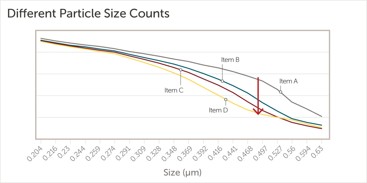
5. Pore Size Distribution & Cutoff Behavior
Sharp cutoff behavior reduces the probability of large-particle breakthrough.
6. Filter Housing Design
6.1 Housing Materials
- Fluoropolymer (PFA)
- High-purity polypropylene
6.2 Flow Path Optimization
Dead zones inside housings increase particle accumulation and contamination risk.
7. Point-of-Use (POU) Filtration
POU filters provide final particle control immediately before slurry reaches the polishing pad.
| Location | Benefit | Risk |
|---|---|---|
| Bulk Supply | High capacity | Downstream contamination |
| Recirculation Loop | Stability | Delayed response |
| POU | Maximum defect control | Frequent replacement |
8. Chemical Compatibility & Extractables
Filters must not introduce ionic contamination or organic leachables.
9. Performance Data & Lifetime Modeling
Filter lifetime depends on:
- Slurry particle loading
- Agglomeration tendency
- Flow rate and shear stress
| Filter Size | Pore Size | Typical Lifetime |
|---|---|---|
| 10-inch | 0.2 µm | 300–500 wafers |
| 20-inch | 0.5 µm | 800–1200 wafers |
10. Failure Modes & Root Cause Analysis
10.1 Filter Rupture
Caused by excessive pressure differential.
10.2 Channeling
Uneven flow leading to particle breakthrough.
10.3 Chemical Degradation
Results in fiber shedding and contamination.
11. HVM Filter Management Strategy
- Pressure drop monitoring
- Wafer-count-based replacement
- Incoming filter qualification
In HVM, filters must be treated as process control devices, not consumables.
12. How to Select CMP Slurry Filters
Key selection criteria:
- Slurry chemistry compatibility
- Required particle cutoff
- Tool integration constraints
- Cost of ownership (CoO)
Filters must be co-optimized with slurry formulation and CMP pad characteristics.
13. Future Trends
Emerging trends include:
- Integrated particle sensors
- Lower extractables polymers
- Node-specific filter standards