Dicing Blade Technology in Semiconductor Manufacturing
Dicing blade technology forms the technical foundation of wafer singulation in semiconductor manufacturing. While the dicing process itself appears mechanically simple, the cutting behavior at the blade–wafer interface is governed by complex interactions between abrasive materials, bonding systems, blade structure, and process parameters. As device geometries shrink and wafer materials become more diverse, dicing blade technology has evolved from basic abrasive cutting into a highly engineered micro-machining system.
This page provides a technical-level explanation of dicing blade technology used in semiconductor wafer cutting. It focuses on the materials used in blade construction, diamond bonding mechanisms, blade structural design, and the physical cutting mechanisms involved during dicing. The objective is to help process engineers and decision-makers understand not only what blade types exist, but why certain blade technologies perform better under specific conditions.
This cluster page supports the main pillar content on Wafer Dicing Blades for Semiconductor Applications and should be read as a deeper technical reference rather than a general overview.
Overview of Dicing Blade Technology
At its core, a dicing blade is a precision abrasive tool designed to remove material in a controlled and repeatable manner. Unlike macro-scale sawing or grinding, wafer dicing operates in a regime where cutting depths, contact areas, and damage zones are extremely small. As a result, blade technology must address challenges that are negligible in conventional machining but critical in semiconductor manufacturing.
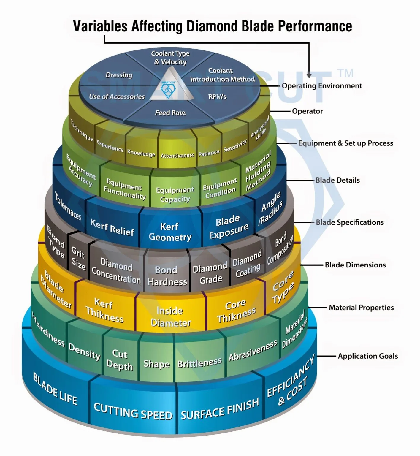
Modern dicing blade technology integrates three essential elements: abrasive material (typically diamond), bonding matrix, and blade geometry. These elements collectively determine cutting efficiency, wear behavior, thermal stability, and surface integrity of the diced wafer. The technology is further constrained by high spindle speeds, narrow kerf requirements, and compatibility with automated dicing saw equipment.
In semiconductor production, dicing blade performance is evaluated not only by cutting speed, but by a combination of yield-related metrics such as edge chipping size, subsurface damage depth, die strength, and process stability over long production runs. This multi-variable optimization is the reason why blade technology selection is process-specific and cannot be generalized across all wafer types.
Materials Used in Dicing Blades
The material system of a dicing blade determines its fundamental cutting capability and durability. In semiconductor applications, the dominant abrasive material is synthetic diamond due to its exceptional hardness and wear resistance. However, diamond alone does not define blade performance; the surrounding bond material plays an equally important role.
Diamond Abrasive Materials
Synthetic diamond particles used in dicing blades are typically produced through high-pressure high-temperature (HPHT) or chemical vapor deposition (CVD) methods. These diamonds are engineered to achieve consistent crystal size, shape, and fracture behavior. Unlike natural diamond, synthetic diamond allows precise control over grit size distribution, which is essential for predictable cutting behavior.
Diamond grit size directly influences material removal mode. Coarser diamond grits promote brittle fracture and higher material removal rates, while finer grits favor controlled micro-chipping and smoother cut edges. The selection of grit size must therefore align with wafer material properties and edge quality requirements.
| Diamond Grit Size (µm) | Typical Application | Cutting Characteristics |
|---|---|---|
| 2–4 | MEMS, image sensors | Minimal chipping, low cutting force |
| 4–8 | Logic and memory wafers | Balanced edge quality and throughput |
| 8–15 | Power devices, thick wafers | Aggressive cutting, higher kerf damage |
Bonding Matrix Materials
The bonding matrix holds diamond particles in place and controls their exposure during cutting. As the blade wears, the bond must release worn diamond grains at an appropriate rate to expose fresh cutting edges. This self-sharpening behavior is a defining feature of effective dicing blade technology.
Common bond materials include resin-based polymers, metal alloys, and electroformed nickel structures. Each bonding system exhibits distinct mechanical properties such as hardness, elasticity, and thermal conductivity, which directly affect blade behavior during cutting.
Diamond Bonding Technologies
Diamond bonding technology is one of the most critical differentiators between dicing blade designs. The bond determines how diamond particles interact with the wafer material and how the blade evolves over its usable life.
Resin Bond Technology
Resin bond blades use polymer-based matrices to retain diamond particles. These bonds are relatively soft and elastic, allowing controlled diamond exposure and reduced cutting forces. Resin bond blades are widely used for applications requiring excellent edge quality and minimal subsurface damage.
The elastic nature of resin bonds helps absorb vibration during cutting, reducing the likelihood of micro-cracking in brittle wafers. However, resin bonds typically exhibit shorter tool life compared to metal bonds, especially when cutting hard materials.
Metal Bond Technology
Metal bond blades employ metallic matrices, often copper- or bronze-based alloys, to hold diamond abrasives. These bonds are harder and more wear-resistant, resulting in longer blade life and dimensional stability.
Metal bond blades are commonly used for thick wafers or hard materials such as silicon carbide. The trade-off is increased cutting force and a higher risk of edge chipping if process parameters are not optimized.
Electroformed Bond Technology
Electroformed blades are produced by electroplating diamond particles onto a metal substrate, typically nickel. In this structure, diamond particles are exposed directly at the blade surface, providing exceptional sharpness and low cutting resistance.
Electroformed blades are often selected for ultra-thin wafers and applications requiring minimal kerf width. However, because they lack a self-sharpening mechanism, their usable life is limited once diamond particles become worn.
| Bond Type | Cutting Force | Edge Quality | Blade Life |
|---|---|---|---|
| Resin Bond | Low | Excellent | Medium |
| Metal Bond | High | Good | Long |
| Electroformed | Very Low | Excellent | Short |
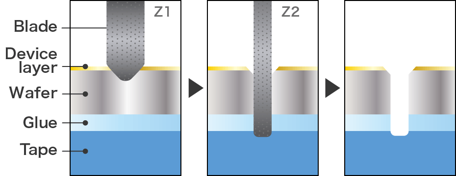
Blade Structure and Cutting Mechanism
Beyond materials and bonding, the structural design of a dicing blade strongly influences cutting stability. Blade core thickness, rim height, diamond layer distribution, and stiffness all affect how the blade behaves under high-speed rotation.
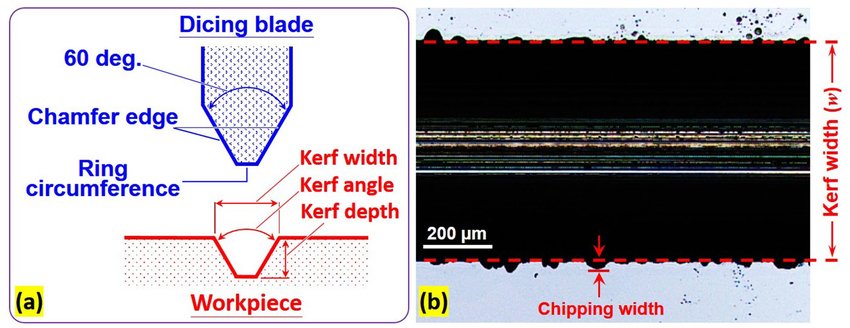
During cutting, material removal occurs through a combination of brittle fracture and micro-ploughing. Diamond particles penetrate the wafer surface, inducing localized stress fields that exceed the fracture toughness of the material. Controlled crack propagation results in material removal, while excessive stress leads to chipping and subsurface damage.
Blade stiffness is particularly critical for thin blades. Insufficient stiffness can cause blade deflection, leading to kerf wandering and uneven cut depth. This is why blade thickness selection must always consider spindle rigidity and feed rate.
Key Factors Affecting Dicing Performance
Dicing blade performance is the result of multiple interacting factors rather than a single dominant variable. Understanding these interactions is essential for stable, high-yield production.
Wafer material properties such as hardness, fracture toughness, and layer structure directly influence blade wear and cutting behavior. Process parameters including spindle speed, feed rate, and cutting depth determine the mechanical and thermal load on the blade.
Environmental factors such as coolant flow and temperature control also play a role by influencing heat dissipation and debris removal. Poor coolant management can accelerate bond degradation and increase cutting defects.
Ultimately, optimal dicing performance is achieved when blade technology, process parameters, and equipment capability are aligned. This alignment forms the basis for the blade selection framework discussed in How to Choose Dicing Blades.
This concludes the technical overview of dicing blade technology. To explore how these technologies are applied in real production processes, continue to the next cluster page on Blade Dicing Process for Semiconductor Wafers.