Dicing Saw Blade Thickness for Wafer Cutting
Dicing saw blade thickness is one of the most critical yet frequently misunderstood parameters in wafer dicing. Blade thickness directly determines kerf loss, influences die mechanical strength, and must remain within the mechanical and dynamic limits of the dicing equipment. Selecting blade thickness is therefore not a simple matter of choosing “as thin as possible,” but rather an engineering trade-off between yield, reliability, and process stability.
This page provides a technical analysis of dicing saw blade thickness from a process engineering perspective. It complements the wafer dicing blades overview and builds upon the equipment constraints discussed in Wafer Dicing Blades Equipment.
Table of Contents
- Why Dicing Blade Thickness Matters
- Common Thickness Ranges of Dicing Blades
- Thickness vs Kerf Loss
- How to Select Blade Thickness
Why Dicing Blade Thickness Matters
Blade thickness governs three fundamental aspects of the wafer dicing process: material removal volume, mechanical stability of the blade, and stress distribution at the die edge. Any change in blade thickness simultaneously affects cutting force, vibration behavior, and kerf geometry.
From an engineering standpoint, blade thickness affects:
- Kerf width and die-to-die spacing utilization
- Blade stiffness and resistance to lateral deflection
- Cutting force magnitude and heat generation
- Die edge chipping and subsurface damage
- Compatibility with spindle torque and flange support
Excessively thin blades may improve die count per wafer but often introduce higher process risk, including blade wandering, increased chipping, and premature blade breakage. Conversely, overly thick blades reduce yield through increased kerf loss and may induce higher mechanical stress on brittle wafers.
Blade Thickness as a Structural Parameter
Blade thickness contributes directly to the second moment of area of the blade cross-section. Even small reductions in thickness can significantly reduce bending stiffness, making the blade more sensitive to spindle runout and cutting force fluctuations.
| Thickness Change | Relative Stiffness Impact |
|---|---|
| -10% | -20% to -25% |
| -20% | -40% to -45% |
| -30% | -60% or more |
This non-linear relationship explains why ultra-thin blades require exceptionally rigid equipment and highly controlled process conditions.
Common Thickness Ranges of Dicing Blades
Dicing saw blade thickness is typically specified in micrometers (μm) and varies depending on wafer material, wafer thickness, and equipment capability. The practical thickness range is narrower than theoretical limits due to blade strength and mounting constraints.
Typical Thickness Ranges by Application
| Application | Typical Blade Thickness | Notes |
|---|---|---|
| Standard silicon wafers | 20–40 μm | Balance of yield and stability |
| Ultra-thin silicon wafers | 15–25 μm | Requires high-rigidity equipment |
| SiC / GaN wafers | 40–80 μm | Higher cutting force and stiffness demand |
| Thick power device wafers | 60–100 μm | Torque and vibration critical |
These ranges are not absolute limits but reflect commonly validated industrial practice. Deviating from these ranges usually requires compensatory adjustments in feed rate, RPM, or blade bond type.
Interaction with Blade Diameter
Blade thickness cannot be evaluated independently of blade diameter. Larger diameter blades experience higher bending moments and therefore require proportionally greater thickness to maintain stiffness.
| Blade Diameter | Minimum Practical Thickness |
|---|---|
| 56 mm | ≥ 20 μm |
| 60 mm | ≥ 25 μm |
| 70 mm | ≥ 35 μm |
Thickness vs Kerf Loss
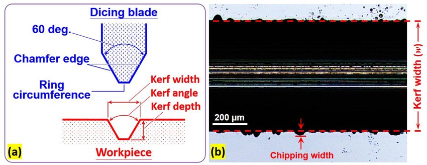
Kerf loss is the most visible consequence of blade thickness selection. Kerf width is approximately equal to blade thickness plus lateral vibration and diamond protrusion effects. In high-precision dicing, kerf loss directly impacts the number of dies per wafer.
Kerf Loss Components
- Nominal blade thickness
- Diamond grit protrusion
- Blade runout and vibration
- Thermal expansion during cutting
While reducing blade thickness reduces nominal kerf width, the actual kerf improvement is often less than expected due to increased blade instability. Thin blades may exhibit greater lateral motion, partially offsetting thickness reduction.
| Blade Thickness | Typical Kerf Width |
|---|---|
| 20 μm | 22–26 μm |
| 30 μm | 32–36 μm |
| 50 μm | 52–58 μm |
For advanced nodes and dense layouts, kerf width variability may be more critical than absolute kerf width.
Impact on Die Mechanical Strength
Blade thickness influences die strength indirectly through edge quality. Thinner blades generally generate lower cutting force but are more susceptible to vibration-induced microchipping. These micro-defects act as crack initiation sites during subsequent handling or packaging.
Die strength failures are often traced back to overly aggressive thickness reduction without sufficient control of cutting stability.
How to Select Blade Thickness
Blade thickness selection should follow a structured decision process that accounts for wafer material, die size, and equipment capability.
Engineering Selection Flow
- Define minimum allowable kerf based on die layout
- Assess wafer material hardness and fracture sensitivity
- Confirm spindle torque and rigidity limits
- Select minimum thickness that maintains stability margin
- Validate through pilot cuts and edge inspection
Equipment Limitation Considerations
Equipment limitations often impose a lower bound on blade thickness. Spindles with limited torque or higher runout require thicker blades to maintain cutting stability.
| Equipment Constraint | Thickness Implication |
|---|---|
| High spindle runout | Increase blade thickness |
| Low torque capacity | Avoid thick, metal-bond blades |
| Large blade diameter | Increase minimum thickness |
Blade thickness selection should always be validated together with blade width and bond type. Additional guidance on holistic blade selection can be found in How to Choose Dicing Blades, which integrates thickness with other key parameters.
Equipment and Process
Thickness-related stability issues are often rooted in equipment mismatch rather than blade design alone. For a deeper understanding of spindle and flange constraints, refer to Wafer Dicing Blades Equipment. Process interactions are further discussed in Blade Dicing Process.
By treating blade thickness as a system-level engineering variable rather than a single optimization target, manufacturers can achieve a balanced improvement in yield, die strength, and process robustness.