Dicing Blade Specifications Guide OD Thickness Grit Size and Exposure
← Back to: Diamond Dicing Blades: The Complete Guide
A dicing blade datasheet typically lists eight or more parameters, and choosing incorrectly on any one of them can result in excessive chipping, premature blade failure, incomplete singulation, or equipment damage. This guide translates each key specification into plain engineering language — what it means, how it affects your process, and how to select the right value for your application.
1. Outer Diameter (OD) and Inner Diameter (ID / Bore)
The outer diameter (OD) of a dicing blade is the overall diameter of the disc including the abrasive rim, measured in millimetres. The OD must be large enough to provide the required cutting depth through the workpiece, tape, and any required clearance below the tape adhesive layer. Standard OD values used in the semiconductor industry are 55.56 mm (2.187 inches) und 76.2 mm (3.0 inches), with 55.56 mm being by far the most common for wafer dicing. Larger OD blades (76.2 mm) are used when greater cutting depth is required, such as for thick substrates or step-cut configurations.
The inner diameter (ID), also called the bore size, is the diameter of the central hole through which the spindle shaft passes. ID must precisely match the spindle hub diameter of your dicing saw. Common bore sizes are 19.05 mm (0.75 inches) und 40.0 mm. Any mismatch between blade ID and spindle hub diameter causes the blade to run off-centre, generating excessive runout, chipping, and potential spindle bearing damage.
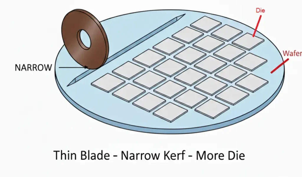
2. Blade Thickness (T) and Kerf Width
Blade thickness (T) is one of the most consequential parameters in dicing process design. It is the nominal width of the abrasive rim and directly governs the width of material removed during cutting — the kerf width. The relationship between blade thickness and actual kerf width is not one-to-one: because diamond grains protrude laterally beyond the blade face, and because the blade oscillates slightly during cutting, the actual kerf is always wider than the nominal blade thickness.
Actual offset depends on blade bond type, diamond grit size, spindle runout, and cutting parameters. Characterise empirically for each process.
Blade thickness selection is primarily driven by the street width in the die layout design. The street width must accommodate the kerf plus edge exclusion zones on both sides of the cut. As die size shrinks and street widths approach 50–80 µm in advanced layouts, blade thickness becomes a yield-limiting variable that must be minimised. Electroformed nickel bond blades, available down to 0.015 mm, are the only viable option when streets fall below 50 µm.
Thinner blades also generate lower lateral cutting forces, which benefits fragile substrates. However, thinner blades are more susceptible to lateral deflection under load, and their reduced mass means they cool less effectively — making coolant optimisation more important. Our guide to dicing coolant selection covers this interaction in detail.
| Anmeldung | Typical Street Width | Recommended Blade Thickness |
|---|---|---|
| Standard Si wafer (logic, memory) | 80–150 µm | 0.040–0.100 mm |
| High-density Si (advanced nodes) | 50–80 µm | 0.020–0.040 mm |
| QFN / BGA package singulation | 200–400 µm | 0.150–0.300 mm |
| LED (GaN on sapphire) | 20–60 µm | 0.015–0.030 mm (electroformed) |
| Glass / quartz substrate | 100–300 µm | 0.100–0.250 mm |
| SiC power device | 100–200 µm | 0.080–0.150 mm |
3. Diamond Grit Size
Grit size describes the average particle size of the diamond abrasive embedded in the blade matrix. It is expressed either as a mesh number (ANSI/FEPA standard, where higher numbers indicate finer particles) or as a micron particle size. The two scales run in opposite directions: a #325 mesh grit is approximately 45 µm particle size, while a #2000 mesh grit is approximately 7 µm.
| Mesh Number | Approx. Particle Size (µm) | Cutting Rate | Surface Finish | Chipping Risk |
|---|---|---|---|---|
| #200 – #325 | 45–75 µm | Sehr hoch | Rough | Hoch |
| #400 – #600 | 25–45 µm | Hoch | Moderate | Moderate |
| #800 – #1200 | 10–25 µm | Moderate | Gut | Niedrig |
| #1500 – #2000 | 5–10 µm | Niedrig | Ausgezeichnet | Very low |
The optimal grit size balances three factors: material hardness, required surface finish, und production throughput. For hard materials like SiC or sapphire, coarser grits are needed because finer-grit blades cannot remove material fast enough without excessive heat buildup — a challenge detailed in our SiC dicing guide. For Si and GaAs, where the primary concern is chipping rather than cutting rate, finer grits (#800 and above) are the standard.
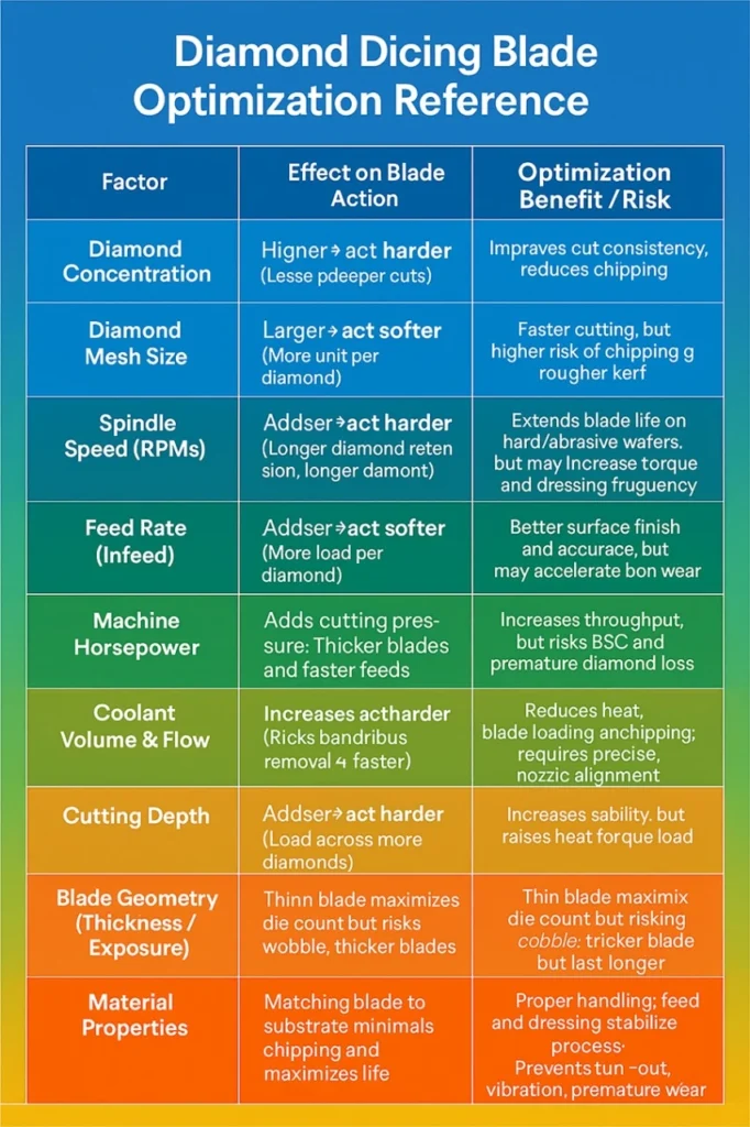
4. Diamond Concentration
Diamond concentration is expressed as a percentage or a standardised concentration number (e.g., C50, C75, C100) representing the volume fraction of diamond within the bond matrix. Higher concentration means more diamond particles per unit volume of blade rim.
Concentration interacts directly with bond type and material hardness to determine cutting behaviour. For hard materials, higher concentration spreads the cutting load across more diamond grains, reducing wear per grain and extending blade life. For soft or ductile materials, lower concentration with a harder bond may be preferred to prevent the blade from cutting too aggressively and loading with swarf.
SiC dicing is a notable case where extremely high diamond concentration (often C100 or above in proprietary formulations) is essential — the material is so hard that a standard-concentration blade would wear to exhaustion within metres of cut. This is one of several reasons why SiC cannot simply be diced with blades specified for silicon.
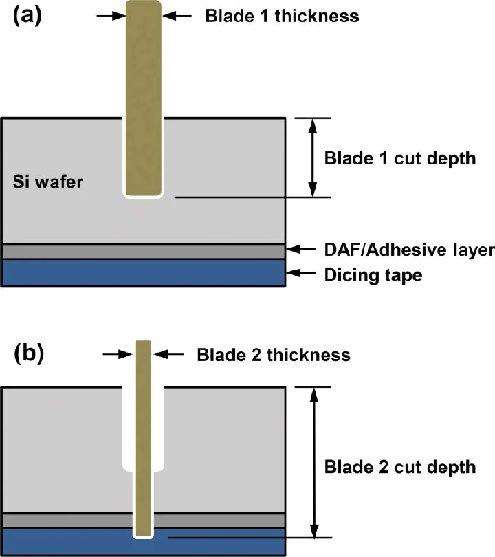
5. Blade Exposure
Blade exposure is the distance by which the abrasive rim of the blade protrudes below the lowest face of the mounting flanges — effectively, the available cutting depth. Setting the correct exposure is essential for achieving complete singulation without grinding into the dicing tape.
Example: 300 µm Si wafer + 100 µm dicing tape = 0.40 mm minimum exposure, so set to 0.45–0.50 mm.
Insufficient exposure results in incomplete cuts — dies remain connected by a thin layer of uncut substrate, causing tearing during pick-up and die edge damage. Excessive exposure causes the blade to cut into the tape adhesive, loading the blade with adhesive material, increasing chipping, and potentially damaging the tape frame. Exposure that is excessively large also increases the unsupported blade length, amplifying vibration and runout.
6. Bond Type Notation in Datasheets
Most blade datasheets use an alphanumeric notation system to describe the full specification. While notation varies between manufacturers, a common format is:
NBC-ZH = Blade series / bond type identifier
27HECC = Diamond grit and concentration grade
100 = OD (mm) or series indicator
0.030 = Blade thickness (mm)
19.05 = Bore ID (mm)
Always request a full datasheet from your blade supplier and confirm every parameter before running production. If in doubt about any notation, consult the manufacturer directly. A full explanation of how bond type interacts with all the parameters above is available in our bond type comparison guide.
7. Quick Reference: Parameter Selection Table
| Parameter | Key Consideration | If Too Large / Too Coarse | If Too Small / Too Fine |
|---|---|---|---|
| OD | Must exceed wafer + tape + clearance depth | Excess blade rim increases runout risk | Incomplete singulation |
| Blade Thickness (T) | Must fit within street width minus exclusion zones | Removes too much material; kerf too wide | Blade deflection; fragility |
| Grit Size | Balance between surface finish and cutting rate | High chipping; rough surface | Slow cutting; loading risk on soft materials |
| Concentration | Match to material hardness and bond type | Overcutting on soft materials; loading | Rapid wear on hard materials |
| Exposure | Wafer thickness + tape thickness + clearance | Cuts into tape; blade loading; chipping | Incomplete singulation; die tearing at pick-up |
For substrate-specific parameter recommendations, the material compatibility chart maps common substrates to recommended bond type, grit, and thickness ranges.
Need a Custom Blade Specification?
Jizhi Electronic Technology can help you determine the exact OD, thickness, grit, and bond type for your substrate and dicing saw. Request a specification consultation at no obligation.
Get a Specification Browse Blade Products8. Frequently Asked Questions
↩ Return to the full guide: Diamond Dicing Blades — The Complete Guide