CMP Polishing Pads: The Complete Guide for Semiconductor Professionals
Everything you need to know about chemical mechanical planarization pads — from material science and groove design to SiC applications, defect control, and selecting the right pad for your process node.
- What Is a CMP Polishing Pad?
- How CMP Pads Work
- Pad Materials & Construction
- Hard vs. Soft Pads: Selection Guide
- Groove Design & Slurry Distribution
- SiC & Advanced Semiconductor Applications
- Pad Conditioning & Lifespan
- Material Removal Rate (MRR) & Key Parameters
- Defect Control: Scratches & Uniformity
- Poreless vs. Porous Pad Structures
- Brands, Specifications & Sourcing
- Buying Guide: Price Factors & Procurement
- FAQ
Certified
サプライヤー
Chemical mechanical planarization (CMP) has evolved from a niche planarization technique into one of the most critical and process-sensitive steps in modern semiconductor manufacturing. Whether a fab is producing leading-edge logic at 3 nm, power devices on 8-inch SiC wafers, or DRAM stacks requiring sub-nanometer topography control, the performance of the CMP polishing pad directly determines yield, throughput, and cost-per-wafer.
This guide is the most comprehensive resource available on CMP polishing pads. It covers every aspect of pad science and engineering — from raw material selection and groove geometry to advanced defect mitigation and next-generation poreless architectures. Whether you are a process engineer optimizing an existing recipe, a procurement manager evaluating suppliers, or a researcher designing a custom planarization process, you will find actionable, technically grounded information here.
1. What Is a CMP Polishing Pad?
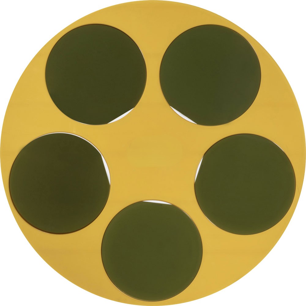
A CMP polishing pad is a precisely engineered consumable that serves as the working surface in chemical mechanical planarization equipment. Mounted on a rotating platen, the pad contacts the front surface of a semiconductor wafer — held face-down by a carrier head — while an abrasive slurry is continuously delivered between the two surfaces. The combination of chemical attack (from the slurry chemistry) and mechanical abrasion (from pad asperities and slurry particles) removes material from elevated topographic features on the wafer surface, progressively flattening it to the nanometer-level planarity required for subsequent lithography and deposition steps.
For a deeper technical overview of the process context, see our dedicated article: What Is a CMP Polishing Pad? The Ultimate Guide.
Why Does Pad Choice Matter So Much?
The pad is not passive. Its surface micro-texture, porosity, hardness, compressibility, groove geometry, and chemical compatibility with the slurry all directly control:
Planarization Efficiency
How effectively the pad removes material from high points while preserving low-lying features — the core metric of CMP quality.
Material Removal Rate
The volumetric rate (Å/min) at which the target film is removed, which governs throughput and process window width.
Within-Wafer Uniformity
Radial and azimuthal variation in removal across a 200 mm or 300 mm wafer, critical for yield at tight nodes.
Surface Defect Levels
Scratch density, micro-scratch depth, and particle contamination on the post-CMP surface, affecting downstream electrical performance.
2. How CMP Polishing Pads Work
The mechanics of CMP material removal are governed by three interacting phenomena: pad-wafer contact mechanics, slurry hydrodynamics, and surface chemistry. Understanding how these interact helps process engineers dial in recipes and diagnose yield excursions. Our detailed article on How CMP Polishing Pads Work provides an in-depth look at each mechanism.
The Three-Body Contact Model
At the microscale, the pad surface is not flat. It is covered with asperities — micro-scale protrusions that constitute the actual contact points with the wafer. Real contact occurs at the tips of these asperities and at abrasive particles trapped between pad and wafer. This three-body contact (pad asperity → slurry particle → wafer surface) is the primary locus of mechanical material removal.
Slurry Delivery & Transport
Slurry is dispensed onto the pad surface and transported radially inward by centrifugal force and groove channels. Pad groove geometry determines how uniformly the slurry is distributed under the wafer at any given moment.
Chemical Passivation Layer Formation
Reactive species in the slurry (oxidizers, complexing agents, pH buffers) react with the wafer surface to form a thin, softer passivation layer on the target film — for example, converting Cu to Cu₂O or SiO₂ to a silanol-rich gel.
Mechanical Removal of Passivation Layer
Abrasive particles (ceria, silica, alumina) borne by the pad asperities abrade away the weakened passivation layer, exposing fresh material for the next chemical cycle. The pad’s hardness controls how aggressively asperities penetrate the slurry film.
Byproduct Removal
Removal products (dissolved ions, spent particles, detached film fragments) are swept away by fresh slurry through groove channels and pad pores, preventing re-deposition defects.
Pad Conditioning (In-Situ or Ex-Situ)
A diamond disk dresser periodically abrades the pad surface, removing glazed and clogged material, restoring asperity height and porosity, and maintaining a stable removal rate over many wafer passes.
3. Pad Materials & Construction
The material composition of a CMP polishing pad determines its mechanical response under polishing conditions, its chemical compatibility with aggressive slurries, and its ability to maintain stable surface texture over thousands of wafer passes. For a thorough comparison of all major pad materials, read: CMP Pad Materials: Polyurethane vs Other Options.
| 素材 | Hardness (Shore D) | 多孔性 | Key Advantage | 代表的なアプリケーション |
|---|---|---|---|---|
| Polyurethane (PU) — filled | 55–65 | Closed-cell micro-pores | High planarization efficiency, tunable hardness | Oxide, W, STI CMP at all nodes |
| Polyurethane — poreless | 60–70 | Near-zero | Ultra-low defect density, advanced nodes | Gate-last, EUV-layer CMP |
| Polyurethane — soft (subpad) | 30–45 | Open-cell foam | High global uniformity, gentle on fragile films | Cu BEOL, low-k dielectric, subpad layer |
| Composite (felt + PU) | 20-35 | High, fibrous | Excellent slurry retention, large-area contact | Legacy oxide, substrate lapping |
| Diamond-impregnated | N/A (rigid) | 低い | Extreme hardness for ultra-hard materials | SiC, GaN, sapphire, diamond substrates |
| Non-woven fiber | 15-25 | 非常に高い | High slurry uptake, cost-effective | Pre-lapping, glass, optics polishing |
Polyurethane: The Dominant Choice
Polyurethane dominates the CMP pad landscape for compelling reasons. The polymer matrix can be formulated across a wide hardness range by adjusting isocyanate-to-polyol ratios, cross-link density, and filler content. Closed-cell micro-pores — typically 20–50 µm in diameter, introduced by hollow microspheres or CO₂ blowing — serve as slurry reservoirs that replenish the contact interface during polishing. The pore size distribution, density, and uniformity are among the most tightly controlled parameters in pad manufacturing, directly impacting both removal rate consistency and defect levels.
Jizhi Electronic Technology manufactures its polyurethane pad series using proprietary formulation chemistry developed through in-house R&D, enabling us to offer pore density and hardness profiles tailored to specific process nodes — from mature 28 nm production to leading-edge FinFET and gate-all-around (GAA) technologies.
4. Hard vs. Soft CMP Polishing Pads: Selection Guide
The single most impactful pad specification decision is hardness. Hard pads and soft pads make fundamentally different trade-offs between planarization efficiency and surface conformance. Our detailed selection guide covers this topic in depth: Hard vs. Soft CMP Polishing Pads: Selection Guide.
🔷 Hard Pads (Shore D 55–70)
- High planarization efficiency — preferentially removes high topography
- Stable removal rate across extended polishing campaigns
- Better step-height reduction for STI and pre-metal dielectric
- Lower conformance — risk of edge exclusion on warped wafers
- Typical example: IC1000™-style pads
- Best for: oxide, W plug, STI, inter-layer dielectric (ILD)
🔹 Soft Pads / Subpads (Shore D 30–45)
- High within-wafer uniformity — conforms to local topography
- Lower shear forces — protects fragile low-k and ultra-thin films
- Often used as the lower layer in a stacked (hard + soft) configuration
- Lower step-height reduction than hard pads
- Best for: Cu BEOL, low-k dielectric, barrier, final surface finishing
- Critical for 300 mm wafers where edge-center uniformity is demanding
The Stacked Pad Stack Strategy
Modern high-volume manufacturing frequently employs a two-layer pad stack: a hard polyurethane top pad bonded to a soft foam subpad. The hard upper layer delivers the planarization efficiency of a rigid surface, while the compliant lower layer absorbs wafer-scale bow and warp, dramatically improving edge-to-center removal uniformity. The compressibility of the combined stack can be tuned by varying subpad thickness and foam density, giving process engineers an additional process knob. For a complete overview of how these pad types are matched to specific device manufacturing steps — from front-end STI through Cu BEOL — see our guide to Semiconductor CMP Polishing Pads.
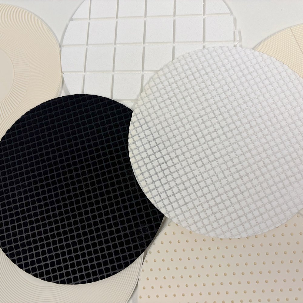
5. Groove Design & Slurry Distribution
The surface of a CMP polishing pad is not flat — it is precisely machined with a network of grooves whose geometry profoundly affects slurry transport, heat dissipation, and polishing stability. Deep-dive analysis of groove geometry and its process impacts is covered in: CMP Pad Groove Design and Slurry Distribution.
| グルーヴ・パターン | Geometry | Slurry Distribution | Best Application |
|---|---|---|---|
| Concentric (K-groove) | Concentric rings, constant pitch | Uniform radial, excellent retention | Oxide, W, general purpose |
| XY Cartesian Grid | Orthogonal grid, equal pitch | Good bi-directional flow, easy to characterize | Cu BEOL, barrier metal |
| Spiral (Archimedean) | Single or multi-arm spiral | Centrifugal pumping effect enhances radial transport | High-throughput, slurry-sensitive applications |
| Perforated (hole array) | Through-holes in addition to grooves | Maximum slurry uptake, excellent for endpoint detection windows | Optical endpoint, in-situ metrology |
| Asymmetric / Custom | Variable pitch, depth, or angle by zone | Tunable radial profile — center-fast or edge-fast correction | Non-uniform incoming wafer topography, advanced node |
Groove width (typically 0.25–1.0 mm), depth (0.3–0.8 mm), and pitch (1.5–6 mm) are the primary design variables. Narrower, deeper grooves increase slurry retention time and can improve removal rate at the cost of reduced contact area and slightly higher defect risk. Shallower grooves reduce the risk of abrasive particle packing but require more frequent re-dressing to maintain transport efficiency.
Jizhi’s application engineering team designs groove patterns using computational fluid dynamics (CFD) modeling to predict slurry film thickness and uniformity before pad fabrication, reducing process development cycles for new applications.
6. SiC, GaN & Advanced Semiconductor Applications
Silicon carbide (SiC) and gallium nitride (GaN) are the defining materials of the power electronics revolution — enabling EV inverters, industrial motor drives, fast-charging infrastructure, and 5G power amplifiers to operate at voltages, temperatures, and switching frequencies that silicon cannot sustain. Both materials impose extreme demands on CMP processes, and by extension, on polishing pads. Our specialist resource on this topic: SiC CMP Polishing Pads for Third-Generation Semiconductors.
Why SiC CMP Is So Difficult
SiC has a Mohs hardness of 9.5 — approaching that of diamond (10) and far exceeding Si (6.5) or SiO₂ (7). The chemical inertness of SiC is equally formidable: its oxidation rate under conventional oxidizing slurries is orders of magnitude slower than silicon, severely constraining the chemical component of the CMP mechanism. The result is that material removal rates on SiC with standard oxide CMP recipes are below 50 Å/min — commercially unacceptable for wafer production.
Key Pad Requirements for SiC CMP
High Hardness & Abrasion Resistance
The pad must resist accelerated mechanical wear from the SiC surface and hard abrasive particles (diamond, ceria) used in SiC slurries.
化学的適合性
Strong oxidizers (KMnO₄, H₂O₂ at high concentrations, Fenton reagents) are used in SiC slurries. The pad polymer must maintain mechanical integrity under aggressive chemical environments.
Thermal Stability
SiC polishing generates more frictional heat than silicon. Pads must maintain stable hardness and modulus up to 60–80°C process temperatures.
Low Sub-Surface Damage
For power device SiC, sub-surface crystal damage from prior lapping steps must be removed during CMP without introducing new dislocation damage — demanding precisely controlled pad compliance.
7. Pad Conditioning & Lifespan Management
A new pad removed from its packaging is not ready to polish. Nor does a pad maintain a consistent surface state over its useful life without active intervention. Pad conditioning — the process of mechanically abrading the pad surface with a diamond disk dresser — is arguably the most impactful process variable that fabs control during ongoing CMP operations. Full conditioning protocols and pad life monitoring strategies are detailed in: CMP Pad Conditioning and Lifespan Management.
Why Conditioning Is Essential
During polishing, three degradation mechanisms simultaneously reduce pad performance:
Glazing (Surface Vitrification)
Mechanical friction and heat partially melt and re-solidify the polyurethane surface, collapsing asperities and reducing the contact area available for slurry-mediated abrasion. Removal rate drops 20–40% in just 10–20 wafer passes on an unconditioned pad.
Pore Clogging
Spent slurry particles, reaction byproducts, and polymer debris pack into pad pores and grooves, reducing slurry uptake capacity and causing non-uniform transport across the pad surface.
Asperity Height Loss (Wear)
Over the pad’s full lifetime, cumulative material loss from both conditioning and polishing progressively reduces pad thickness, eventually reaching a minimum usable thickness that defines end-of-life.
Break-In Protocol
A new pad requires a structured break-in (also called “seasoning”) before production polishing. Standard practice involves 30–100 conditioning sweeps on a wet, freshly slurried pad surface before the first production wafer is polished. This process micro-fractures the surface skin, opens pores to slurry access, and establishes a stable, reproducible asperity distribution. Skipping break-in leads to a high-variance “run-in” region at the start of the pad’s life curve that can account for dozens of yield-risk wafers.
8. Material Removal Rate (MRR) & Key Process Parameters
Material removal rate is the primary productivity metric of any CMP process. It determines how long each polish step takes and, in high-volume manufacturing, directly translates to cost-per-wafer. Understanding what controls MRR and how to optimize it without sacrificing surface quality is central to CMP process engineering. Our dedicated analysis: CMP Material Removal Rate and Pad Parameters.
The Preston Framework and Its Limits
The Preston equation (MRR = Kp × P × V) provides a first-order model: removal rate scales linearly with down-force pressure (P, typically 1–6 psi on 300 mm tools) and relative velocity (V, determined by platen and carrier RPM, typically 50–120 rpm). The Preston coefficient Kp encapsulates pad and slurry material properties. In practice, MRR deviates from Preston linearity at both very low pressures (where the hydrodynamic slurry film becomes load-bearing, reducing contact) and very high pressures (where pad deformation reduces asperity effectiveness and defect generation increases).
| パラメータ | 典型的な範囲 | Effect on MRR | Effect on Defects |
|---|---|---|---|
| Down-force pressure | 1–6 psi | ↑ with pressure (Preston) | ↑ scratch risk at high P |
| Platen / carrier RPM | 30–120 rpm | ↑ with velocity | Neutral at moderate V |
| Slurry flow rate | 100–300 mL/min | Plateau above saturation flow | ↓ with higher flow (dilution) |
| Pad hardness (Shore D) | 35–65 | ↑ Kp with harder pad | ↑ with harder pad |
| Conditioner down-force | 2–8 lbf | ↑ with harder conditioning | ↑ micro-scratch at high force |
| Slurry particle size | 60–200 nm (d50) | ↑ with larger particles | ↑ strongly with large particles |
9. Defect Control: Scratches, Uniformity & Surface Quality
Post-CMP surface defects represent one of the top yield loss mechanisms in advanced semiconductor manufacturing. Micro-scratches, pits, slurry particle residues, and edge exclusion non-uniformities from the CMP pad-wafer interaction can cause dielectric breakdown, contact resistance shifts, and reliability failures in finished devices. Our complete defect analysis guide: CMP Pad Defect Control: Scratches and Uniformity.
Primary Defect Types and Their Pad-Related Origins
Micro-Scratches
Caused by over-conditioned pad asperities, agglomerated slurry particles, or pad debris embedding in the polishing interface. Harder pads pose greater scratch risk at equivalent pressure.
Pitting & Corrosion
Aggressive slurry chemistry combined with pad surface channeling can create locally high chemical exposure, particularly on Cu and low-k surfaces. Groove geometry affects local chemical concentration.
Edge Exclusion (EE) Non-Uniformity
Insufficient pad conformance at the 300 mm wafer edge causes higher removal at the edge (edge-fast) or lower removal (edge-slow). Stacked pad design and retaining ring pressure are the primary controls.
Particle Residues
Spent slurry particles, pad debris, and reaction byproducts re-deposited on the wafer surface. Linked to inadequate groove drainage and post-CMP cleaning process compatibility.
Within-Wafer Non-Uniformity (WIWNU) Metrics
WIWNU — expressed as the standard deviation (1σ) of remaining film thickness across the wafer after CMP, normalized to mean thickness — is the primary pad performance uniformity metric. Sub-1% WIWNU (1σ) is expected for oxide CMP at 28 nm and below. Achieving this requires matched pad compressibility, retaining ring geometry, and slurry delivery system design. Jizhi’s pad characterization laboratory measures WIWNU on sample wafers from every production lot as a quality release criterion.
10. Poreless vs. Porous Pad Structures: Next-Generation Technology
The transition from macro-porous to micro-porous to poreless pad structures represents the most significant architectural evolution in CMP pad technology over the past decade. For a detailed technology comparison, see: Poreless CMP Pads vs. Porous Structure.
Conventional Porous Pads
- Micro-pores (20–50 µm) serve as slurry reservoirs
- Proven performance across all major CMP applications
- Variable pore size distribution — source of lot-to-lot MRR variation
- Pore collapse risk under high conditioner force
- Excellent slurry retention, forgiving to slurry flow interruptions
- Lower cost — commodity availability from multiple suppliers
Poreless / Near-Poreless Pads
- Slurry transport via groove network only — no pad-internal reservoir
- Ultra-consistent surface texture — near-zero lot variation in Kp
- Dramatically lower defect density — no pore-related debris
- Requires precise, stable slurry flow — no flow interruption tolerance
- Ideal for EUV-layer, gate-all-around, and 3D NAND step-height CMP
- Higher unit cost, but higher wafer-per-pad yield can offset premium
Jizhi Electronic Technology offers both poreless and conventional porous pad series, allowing customers to select the optimal balance of performance, process stability, and economics for each CMP step in their integration scheme.
11. CMP Polishing Pad Brands, Specifications & the Case for Domestic Alternatives
A comprehensive brand-by-brand comparison of specifications, certifications, and price-performance ratios is available in our dedicated resource: CMP Polishing Pad Brands Comparison. Below is a summary of the competitive landscape as of April 2026.
Global Market Leaders
The CMP polishing pad market has historically been dominated by a small number of Western suppliers — Entegris (formerly Cabot Microelectronics / CMC Materials), 3M, and a handful of specialty manufacturers. The IC1000™ family of polyurethane pads, originally developed by Rodel (now Entegris), became the industry standard reference for oxide CMP, and its specifications are still used as the benchmark for competitive qualification. For IC1000 specifications and alternatives, see: IC1000 CMP Pad Specs and Alternatives.
The Rise of High-Quality Domestic Alternatives
The geopolitical landscape of 2024–2026 has accelerated the qualification of domestically produced CMP pads across Asia — particularly in China, South Korea, and Taiwan — as fabs and equipment makers seek to de-risk supply chains that had become over-concentrated in a small number of Western sources. Jizhi Electronic Technology sits at the forefront of this transition, offering pads that are performance-qualified against IC1000 and NexPlanar benchmarks while offering:
Significant Cost Advantage
15–30% lower landed cost versus equivalent Western-branded pads for the same performance tier, driven by domestic manufacturing scale and optimized logistics.
Rapid Delivery
In-stock inventory of all standard SKUs with 3–7 day lead times for most Asia-Pacific destinations, versus 8–16 week lead times common for import orders from Western suppliers.
Technical Co-Development
Direct access to our pad materials R&D team for process qualification support, custom formulation requests, and on-site application engineering — difficult to obtain from large multinational suppliers.
Full Documentation
COAs, SDS, process characterization data packages, and batch-level metrology reports provided with every shipment — meeting the documentation requirements of ISO-certified fabs worldwide.
For applications that fall outside standard product specifications — unusual substrate geometries, non-standard wafer sizes, novel dielectric stacks, or highly aggressive slurry chemistries — Jizhi offers a structured co-development program. Learn about our full development and qualification workflow in: Custom CMP Polishing Pad Solutions.
12. Buying Guide: Price Factors, Procurement & Supplier Qualification
Purchasing CMP polishing pads involves more than comparing unit prices. Total cost of ownership (TCO) considerations — including pad life, wafer-per-pad yield, post-CMP defect rework rates, and qualification costs — often dominate the economic analysis. Our full procurement guide: CMP Polishing Pad Price Factors and Buying Guide.
What Drives CMP Pad Pricing
| Cost Factor | Impact on Price | Buyer Leverage |
|---|---|---|
| Pad diameter (200 mm vs 300 mm) | 300 mm pads are 2.25× larger by area — direct material cost impact | Low — process-determined |
| Polyurethane formulation complexity | Specialty low-defect or SiC formulations carry 30–80% premium over standard | Specify actual process requirements, not maximum specification |
| Groove machining | Custom groove patterns add tooling amortization cost (~10–20% for small volumes) | Standardize on common patterns; custom only where process-critical |
| Lot size / annual volume | Volume commitments of >500 pads/year typically unlock 8–15% price breaks | Negotiate annual blanket orders with call-off flexibility |
| Certification & documentation requirements | IATF 16949, SEMI S2/S8, full COA packages add 5–15% overhead at qualified suppliers | Clarify minimum needed documentation early in supplier selection |
| Freight & import duties | Can add 15–30% to Western-branded pads imported into Asia | Qualify domestic suppliers or regional distribution hubs |
Supplier Qualification Checklist
Request Process Characterization Data
Ask for removal rate vs. pressure curves, WIWNU data on your target film stack, and pad-to-pad repeatability data (coefficient of variation in removal rate, <5% is good).
Conduct Side-by-Side Benchmarking
Run qualification lots with identical recipe parameters (pressure, velocity, slurry, conditioning) comparing the new pad against your current qualified pad. Target metrics: MRR within ±10%, WIWNU within ±0.5% (1σ), defect density within ±20%.
Verify Lot-to-Lot Consistency
Request data from three or more production lots. Standard deviation in removal rate across lots should be <5%. This is often the differentiator between commodity and premium pads.
Assess Supply Chain Resilience
Confirm in-stock inventory levels, maximum surge capacity, lead time commitments, and backup raw material sourcing. A supplier unable to scale up for a production surge is a yield risk.