Dicing Blade Wear Too Fast Heres What to Check
← Back to: Diamond Dicing Blades: The Complete Guide
When a dicing blade wears out in half the expected service life, the instinct is often to blame the blade supplier. In practice, premature blade wear is almost always a process or application issue — the blade is being asked to do something outside its design envelope. This guide walks through the eight most common causes of abnormally fast blade wear and provides a systematic checklist for diagnosing each one.
1. First: Establish Your Wear Baseline
Before diagnosing premature wear, you need a precise definition of “normal” wear for your specific blade-material-parameter combination. Blade life is expressed in linear metres of cut — the total length of kerf produced before the blade must be replaced. For a given substrate, blade specification, and parameter set, this number should be consistent to within ±20% across blade lots from the same supplier.
If you do not have a documented baseline, you cannot objectively determine whether wear is “premature.” Establish one by measuring the OD of a new blade (with a micrometer or the saw’s blade measurement function), tracking metres cut to end-of-life across three consecutive blades, and recording the average OD loss at end-of-life. That data set is your baseline. Every future blade is then compared against it.
Cause 1 — Bond Too Soft for the Material
The bond matrix must match the hardness of the workpiece. A bond that is too soft is eroded by the workpiece faster than the diamond grains are consumed — essentially the workpiece grinds away the blade body rather than being cut by it. This is the most common blade-specification mismatch that causes fast wear.
It manifests most often when a blade qualified for a softer material (e.g., Si resin bond blade) is used on a harder substrate (glass, quartz, alumina) without re-qualification. The workpiece rapidly erodes the soft resin matrix, producing dramatic blade diameter reduction within the first few wafers.
Check: Compare the blade bond type against the recommendations in the material compatibility chart. If the bond is softer than recommended, switch to the correct bond type before investigating other causes.
Cause 2 — Incorrect or Insufficient Diamond Concentration
Diamond concentration determines how many abrasive grains share the cutting load per unit volume of blade rim. At low concentration, fewer grains share the work — each grain must remove more material per pass, accelerating individual grain wear and causing them to be shed from the matrix before they have contributed their full abrasive potential.
For hard materials (SiC, sapphire, alumina), high concentration (C100 or above) is essential. Using a standard-concentration blade on SiC is the single most common cause of catastrophic blade wear in compound semiconductor manufacturing. Each grain is overloaded and is shed almost immediately after exposure, consuming blade diameter at a rate 10–20× above normal.
Check: Verify the blade concentration grade against the application requirement. If the supplier datasheet does not explicitly state a concentration grade, contact the supplier for confirmation.
Cause 3 — Feed Rate Too High
Feed rate controls the volume of material each diamond grain must remove per revolution. At high feed rates, each grain impact is more energetic, increasing the probability of grain fracture or premature shedding. On softer bond blades, the bond matrix surrounding each grain also experiences higher stress at high feed rates, accelerating matrix erosion around the grain base and causing premature grain loss.
Feed-rate-induced wear is easy to identify: wear rate increases roughly linearly with feed rate above the optimal range. A 50% increase in feed rate that produces a 50–60% increase in wear rate confirms feed rate as the primary driver.
Check: Reduce feed rate by 30% and measure wear rate over one full blade life. If wear rate falls proportionally, feed rate was the cause. Rebalance feed rate versus blade life cost to find the optimum operating point.
Cause 4 — Over-Dressing
Dressing is necessary, but each dress pass removes blade material. If dressing frequency is higher than process conditions require — or if dress depth per pass is too aggressive — the cumulative blade material consumed in dressing can account for a significant fraction of total blade life loss.
Over-dressing is particularly common in facilities where dressing is performed on a fixed time schedule rather than triggered by process data. A blade that is dressed every 10 wafers regardless of spindle load or chipping data will be over-dressed on easy cuts and under-dressed on demanding ones.
Check: Review dressing logs. Calculate the total dress passes per blade life and the estimated OD consumed in dressing versus in cutting. If dressing accounts for more than 20–25% of total OD loss, the dressing schedule is too aggressive. Switch to data-driven dressing triggers as described in our dressing tutorial.
Cause 5 — Coolant Problems
Coolant does more than cool — it lubricates and flushes. Insufficient lubrication increases friction at every grain contact point, generating more heat and greater mechanical stress on both the diamond grain and the bond matrix. Over time, this thermal and mechanical overload accelerates bond erosion and grain shedding.
Three coolant failure modes cause premature wear:
- Insufficient flow rate: Heat accumulates at the cutting zone, softening the bond matrix and accelerating erosion. Verify flow rate at both nozzles with a calibrated flow meter — flow sensor readings at the pump can overstate actual delivery if nozzles are partially blocked.
- Blocked or misaligned nozzles: Even if total flow is correct, misdirected flow does not reach the blade–workpiece interface. Inspect nozzle alignment visually with the spindle running.
- No coolant additive (plain DI water): DI water provides no boundary lubrication. Switching from plain DI water to a formulated coolant additive with lubricity enhancers typically reduces wear rate by 15–30% on metal bond blades with no other process changes.
Cause 6 — Wrong Grit Size for the Application
Finer diamond grit means more grains per unit volume of blade rim, each removing a smaller amount of material per pass. For a given feed rate, finer grit distributes the cutting load across more contact points, reducing wear per grain. However, if finer grit is used on a very hard material (SiC, sapphire), the reduced material removal rate per grain means each grain must make many more passes before the material is removed — heat accumulates, and grain fracture rate increases.
Conversely, coarser grit on a soft material removes material so aggressively that the bond matrix is undermined before grains are worn — grains are shed prematurely with their abrasive potential unconsumed. Both mismatches accelerate wear rate compared to the optimal grit for the specific material.
Check: Cross-reference current grit against the material-specific grit recommendations in the blade specifications guide.
Cause 7 — Abrasive Contamination in the Kerf
Hard particles on the wafer surface — from upstream process steps such as grinding, CMP, or laser processing — can act as additional abrasive contacts against the blade rim as the cut progresses. If the incoming wafer surface is contaminated with SiC or Al₂O₃ particles from grinding wheel debris, these hard particles are harder than the blade bond matrix and will erode it on contact.
This cause is identified by sudden onset of fast wear on a process that previously ran normally, coinciding with a change in upstream processing or wafer cleaning. Inspect incoming wafer surfaces under dark-field illumination before dicing to check for surface particle contamination.
Cause 8 — Spindle Runout and Lateral Vibration
Elevated spindle runout causes the blade to oscillate laterally during cutting. Each lateral oscillation forces the blade rim against the kerf wall at an angle, generating abrasive contact between the blade’s side face and the cut material — a form of wear that is entirely separate from the intended cutting action at the blade’s bottom edge. This side-wall abrasion can contribute substantially to OD loss without producing useful cutting.
Runout-driven wear is identifiable by inspecting the blade side faces for unusual wear marks or surface roughening, and by correlating elevated wear rate with elevated TIR measurements. Clean and inspect flanges; replace worn flanges; verify spindle TIR with a dial indicator.
Rapid Diagnosis Checklist
| # | Check | If Yes → Action |
|---|---|---|
| 1 | Bond type matches substrate hardness recommendation? | If No: switch to correct bond type first before other changes |
| 2 | Diamond concentration matches material hardness? | If No: upgrade to correct concentration grade |
| 3 | Feed rate within qualified process window? | If above window: reduce 20–30%; re-measure wear rate |
| 4 | Dressing frequency and depth within guidelines? | If excessive: switch to data-driven dressing trigger |
| 5 | Coolant flow rate at spec; nozzles clean and aligned? | If No: clean nozzles; verify flow; add lubricant additive |
| 6 | Grit size correct for substrate per material chart? | If mismatched: re-specify grit per material recommendation |
| 7 | Incoming wafer surface free of hard particle contamination? | If contaminated: improve upstream cleaning; inspect with dark-field |
| 8 | Spindle TIR within spec (≤2–3 µm)? | If elevated: clean flanges; replace worn flanges; check spindle |
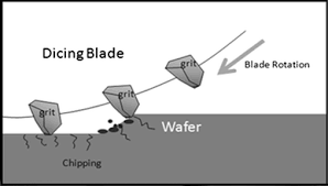
For context on how wear rate interacts with chipping and process quality, see the companion troubleshooting articles on dicing blade chipping そして blade loading.
Blades Wearing Out Faster Than Expected?
Jizhi Electronic Technology’s application team can review your blade specification, process parameters, and wear data to identify the root cause and recommend corrective action. Our resin bond, metal bond, and nickel bond blades are formulated for maximum life in their respective material ranges.
Request a Wear Analysis View Dicing Bladesよくある質問
↩ Return to the full guide: Diamond Dicing Blades — The Complete Guide