CMP Polishing Pad:Types, Selection & Performance Guide
Everything process engineers need to know about CMP polishing pads — covering material types, hardness trade-offs, groove geometry, pad conditioning, multi-stack configurations, lifetime management, and selection criteria for every major CMP application in semiconductor manufacturing.
- The Role of the Polishing Pad
- Pad Materials and Construction
- Hardness Trade-Off: Performance vs Defects
- Groove Geometry and Slurry Transport
- Pad Types Comparison Table
- Pad Conditioning: The Critical Variable
- Pad Lifetime Management
- Multi-Stack and Fixed-Abrasive Pads
- Pad Selection Guide by Application
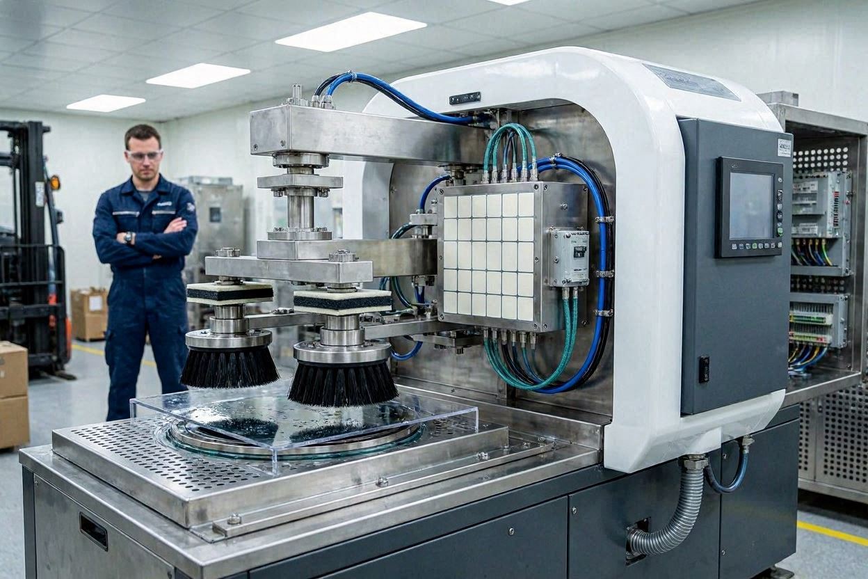
The Role of the Polishing Pad in CMP
The polishing pad is the physical interface between the slurry and the wafer — yet it is far more than a passive carrier. The pad’s mechanical properties govern how uniformly polishing pressure is distributed across the wafer; its surface texture determines how efficiently slurry is transported to and retained at the polishing interface; and its conditioning response defines how removal rate stability evolves over the pad’s lifetime.
In the CMP process, the pad and the slurry function as an inseparable system. A well-chosen slurry paired with a poorly matched pad will underperform relative to either component’s individual capability. Conversely, a meticulously formulated slurry can be compromised by a glazed, worn, or incorrectly conditioned pad. For this reason, polishing pad qualification should always be performed in conjunction with slurry qualification, never independently. See the CMP Complete Guide and the CMP Slurry Guide for the broader context.
Pad Materials and Construction
The vast majority of production CMP pads are constructed from polyurethane — a polymer whose mechanical properties (modulus, hardness, viscoelasticity) can be precisely tuned through formulation chemistry to meet the requirements of different CMP applications. Polyurethane pads are manufactured by casting the polymer into a sheet form, then cutting or punching to the required platen size (typically 20–22 inches diameter for 300 mm tools).
Closed-Pore vs Open-Pore Structures
Conventional polyurethane CMP pads have a closed-pore microstructure created by incorporating hollow microspheres (typically polymethyl methacrylate, PMMA, or blown using chemical foaming agents) into the polymer matrix during casting. These pores serve two critical functions: they reduce the effective modulus of the pad surface layer, improving surface contact uniformity; and as the pad is conditioned and the surface is abraded away, newly opened pores continuously refresh the pad surface texture, maintaining slurry hold-up and transport capability.
The pore size, density, and distribution within the pad are tightly controlled manufacturing parameters. Larger pores and higher pore density create a softer, more compliant pad with better slurry retention but reduced planarization efficiency. Smaller, denser pores give a harder pad with better planarization but reduced slurry retention and potentially higher defect density.
Felt / Impregnated Pads
A second category of CMP pads uses a polyurethane-impregnated non-woven felt structure. These pads are significantly softer and more compliant than cast polyurethane pads and are used primarily as sub-pads in two-layer pad stacks or as final-buff pads for surface finish improvement. Their high compliance allows them to conform closely to local surface topography, making them effective at removing haze and light surface defects but poor at global planarization.
The Hardness Trade-Off: Planarization vs Defects
Pad hardness is the most critical single parameter in pad selection, and it embodies the fundamental tension in CMP process engineering: the same hardness that delivers superior planarization efficiency also tends to increase scratch defect density.
Hard Pads (e.g., IC1000 class)
- Shore D hardness: 55–65
- High global planarization efficiency
- Excellent within-wafer uniformity on raised features
- Less conformance to local topography — reduces dishing
- Higher contact stress at asperities → higher scratch risk
- Preferred for: oxide ILD, STI, tungsten plug CMP
Soft Pads (e.g., Politex / SUBA class)
- Shore A hardness: 30–50
- High conformance to local and global topography
- Lower contact stress → fewer scratches, better surface finish
- Lower planarization efficiency — higher dishing in wide features
- Better slurry retention
- Preferred for: copper buff/finish step, final surface cleaning
The solution to this trade-off in production is the two-platen approach: the primary polishing platen uses a hard pad for bulk material removal and planarization, while the secondary platen uses a soft pad for a brief over-polish / buff step that removes surface defects introduced by the hard pad without re-introducing planarization non-uniformity. This approach is standard in copper CMP modules at all advanced fabs.
Groove Geometry and Slurry Transport
Polishing pads are manufactured with a pattern of grooves on their surface that serve the critical function of distributing slurry evenly across the pad surface and transporting it to the pad-wafer contact zone. Without grooves, slurry would pool in the centre of the pad and starve the outer radii, creating severe radial removal rate non-uniformity.
Common Groove Patterns
- Concentric rings: Simple circular grooves concentric with the pad centre. Provide effective radial slurry distribution but limited circumferential mixing. The most common pattern for general oxide and STI CMP.
- X-Y grid (perforated): Square or rectangular grid pattern. Provides excellent slurry distribution in all directions and effective transport of slurry reaction by-products away from the polishing interface. Preferred for copper CMP where reaction product removal is important.
- Spiral: Continuous spiral groove from pad centre to edge. Combines properties of concentric and grid patterns. Provides smooth, continuous slurry renewal. Used in some tungsten and barrier CMP applications.
- Radial: Grooves running from centre to edge. Promotes centrifugal slurry transport. Can cause circumferential removal rate variation if not combined with other groove elements.
Groove width and depth also matter: wider and deeper grooves provide more slurry reservoir capacity and allow larger slurry flow rates, but they also reduce the effective pad contact area (the “land” area between grooves), which can reduce removal rate. Typical groove width is 0.5–1.5 mm; depth is 0.4–1.0 mm.
CMP Pad Types: Comparison Table
| 垫子类型 | 建筑 | 硬度 | Planarization | 缺陷风险 | 典型应用 |
|---|---|---|---|---|---|
| IC1000 class (hard) | Cast polyurethane, closed-pore | Shore D 58–65 | 优秀 | Medium–High | Oxide ILD, STI, W plug, Cu bulk |
| IC1010 / IC1400 (medium) | Cast polyurethane, closed-pore | Shore D 50–58 | 良好 | 中型 | General purpose, Cu barrier step |
| Politex / SUBA (soft) | PU-impregnated felt | Shore A 35–50 | 低 | 非常低 | Cu buff/finish, final polish, low-k |
| Two-layer stack (hard/soft) | Hard polyurethane + soft sub-pad | Composite | 非常好 | Low–Medium | Cu dual-damascene, barrier CMP |
| Fixed-abrasive pad | Abrasive embedded in polymer matrix | 高 | 优秀 | Very Low (no free abrasive) | STI (slurry-free), oxide, specialty |
| Microreplication pad | PU with 3D-structured surface features | Tunable | 优秀 | 低 | Advanced nodes, hybrid bonding prep |
Pad Conditioning: The Critical Variable
Pad conditioning is the process of mechanically abrading the pad surface with a diamond-tipped conditioner disk during or between wafer polishing runs to restore the surface texture that degrades through “glazing.” It is not an optional maintenance step — without conditioning, CMP removal rates typically drop 20–40% after the first 10–20 wafer passes as the pad asperities are progressively flattened by polishing contact.
Glazing Mechanism
During polishing, mechanical contact between the pad and wafer, combined with the heat generated by friction, causes the pad surface asperities to plastically deform and flatten. Simultaneously, slurry reaction by-products and abraded material can fill and clog the pad’s pores. Both effects reduce the effective surface roughness that allows slurry to be trapped and transported at the polishing interface — this is “glazing.” A glazed pad has a characteristically smooth, shiny appearance and delivers substantially reduced removal rate.
Diamond Conditioner Disk Design
The conditioner disk is a metal substrate embedded with diamond grit particles — typically 100–500 µm in size — that abrade the pad surface as the disk sweeps across it under controlled downforce (typically 2–6 lbs). Diamond grit size and distribution density determine the aggressiveness of conditioning and the surface roughness (Ra) of the conditioned pad. Coarser grit conditions more aggressively, maintaining higher removal rates, but generates more pad wear debris that can contribute to defects. Finer grit conditioning is gentler and preferred for applications where defect density is the primary concern.
In-Situ vs Ex-Situ Conditioning
In-situ conditioning occurs simultaneously with wafer polishing — the conditioner disk sweeps the pad surface while the wafer is being polished on a different zone of the same platen. This approach maintains steady-state pad surface roughness and removal rate and is the production standard. Ex-situ conditioning performs a conditioning sweep between wafer runs, while the platen is idle. Ex-situ conditioning is gentler and is used for final pad break-in or for applications where in-situ conditioning debris is a defect concern.
Pad Lifetime Management
CMP pad lifetime — measured in number of wafer passes or polishing time — is determined by the progressive degradation of pad thickness through conditioning wear, the accumulation of slurry residue and by-products within the pad structure, and the evolution of pad mechanical properties with use. Expired pads must be replaced on a defined schedule before their performance degrades below specification, but premature replacement wastes expensive consumable material.
- Thickness monitoring: Pads have a minimum usable thickness specification (typically 50% of new pad thickness). Continuous pad thickness monitoring — using in-situ optical sensors or periodic manual measurement — enables data-driven replacement scheduling.
- Removal rate trending: Plotting mean removal rate per wafer run over pad life as a statistical process control (SPC) chart reveals performance degradation trends that predict approaching end-of-life before the pad actually fails specification.
- Conditioner disk replacement: Conditioner disk wear directly impacts the quality of pad conditioning and, hence, pad performance. Disk replacement intervals must be defined and adhered to.
- Pad storage: Unused pads must be stored flat in a cool, dry environment. Stack storage on their edges causes permanent pad distortion. Follow manufacturer storage guidelines strictly.
Multi-Stack and Fixed-Abrasive Pads
Two-Layer Pad Stacks
A two-layer pad stack combines a hard, closed-pore polyurethane polishing layer on top with a softer, more compressible sub-pad underneath. The sub-pad acts as a mechanical compliance layer that dampens thickness variations in the platen surface and allows the hard polishing layer to maintain more uniform contact across the wafer. The combined mechanical response provides better global planarization than a soft pad alone while reducing the contact stress peaks that cause scratches with a purely rigid hard pad. Two-layer stacks are the dominant configuration for copper dual-damascene CMP in advanced fabs.
Fixed-Abrasive Pads
Fixed-abrasive (FA) pads embed the abrasive particles directly into the pad surface in a structured polymer matrix, eliminating the need for free abrasive slurry during polishing. The pad surface contains millions of precisely shaped abrasive “caps” that are gradually consumed during polishing, continuously releasing fresh abrasive. FA pads offer extremely low defect density (since there are no free large particles in the polishing environment) and excellent pattern density-independent removal — making them attractive for STI CMP. Their primary limitation is cost and the complexity of the conditioning process required to activate the abrasive surface.
Pad Selection Guide by Application
Selecting the correct pad for a specific CMP application requires balancing planarization efficiency, defect density, removal rate, and pad lifetime requirements. The table below provides application-specific guidance. Always validate pad selection in combination with the slurry system — refer to the CMP Slurry Guide for the companion slurry selection guidance.
JEEZ CMP Polishing Pads
JEEZ supplies hard, soft, and multi-layer CMP pad configurations covering oxide ILD, STI, copper dual-damascene, and advanced packaging applications. Custom groove patterns and dimensions are available. Contact JEEZ to discuss your pad requirements, or explore the CMP Defect Guide to understand how pad selection impacts yield.
Find the Right CMP Pad for Your Application
JEEZ engineers are ready to help you select and qualify the optimal polishing pad for your CMP process. Contact us for samples or technical consultation.
Contact JEEZ →